

Cylinder Head-Aches !! Part 3
- Richard Long
- Aug 4, 2022
- 3 min read
Cylinder Head Autopsy
We are now heading back through the cylinder head in the opposite direction; note that the inlet & exhaust orientation has now changed.
Section 7:
In this section we can see the inlet and exhaust ports with combustion chambers. The spark plug hole is now visible as is the coolant cavity that encircles the spark plug tube. Interesting how the intake port is narrow at the manifold flange end. Also of note, is the different length of the valve guide bore holes. It is however the intake valve guide which is longer than the exhaust guide even though it is offered less support. Once again, the thin wall thickness between coolant cavity and valve train section of the head is clear to see in Fig.26(below).

Section 8:
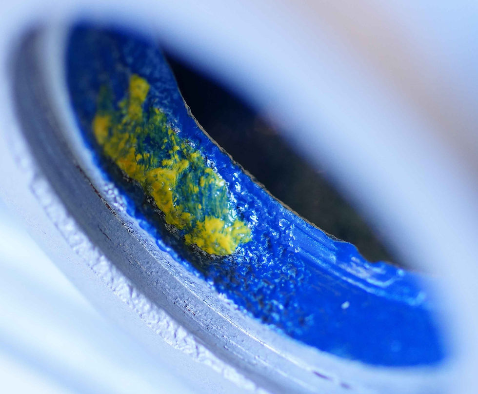
In Fig.27(below) you can see a truly cavernous coolant chamber concentrated around the hot exhaust port. Some quite deep corroded pitting is highlighted in yellow at sporadic points. From this view, you can also see the intake port bending around the diagonal push rod tube. Interestingly, the aluminium was measured at just 0.184” (4.68mm) total thickness above the exhaust port and could be the reason for cracking in this area.

Section 9:
Here is our old friend corrosion again.
In Fig.28 & 29(below); as you can see it has penetrated about half the alloy wall thickness.


This area was one of the most badly corroded internal areas discovered; in fact an additional smaller cross-section cut was made, to help reveal the extent of the damage in Fig.30(below).

The overall wall thickness in this area measured 0.267” (6.78mm) and when measured in the corroded area it measured just 0.105” (2.67mm) making that a loss of 0.162” (4.11mm) !!
Section 10:
This slice again shows the cylinder head fixing drilling's with dowel counter bores top & bottom.
In Fig.31(below) you can see how the casting accommodates the exhaust push rod tube, plus the mould seam is clearly visible.

Another smaller cross-section was taken (Fig.32(below)) to allow a better understanding of how the coolant is circulated around the exhaust port. A surprising feature of this section is just how thin the alloy wall thickness is underneath the exhaust port, a mere 0.157” (4.00mm) which must be taken into consideration when resurfacing cylinder head gasket faces.

The second face of the small cross section (Fig.33(below)) shows the inclined valve guide bore hole, valve spring seat and the now familiar coolant passage that allows for movement between the cylinder block and head. These are the areas that are usually repaired by Tig welding. Less easy to repair is the corrosion eating its way through the exhaust port wall. Some folk like to re-shape and grind the port walls in a bid to improve performance; again Fig.33 shows why care should be taken when doing this !!

Section 11:
This section shows us, perhaps, the best example of the intake manifold securing fixing breaching the push rod tube via Fig.34(below).
The spark plug tube and spark plug threads can also be seen in section. No real signs of corrosion here and you can see the rocker shaft platforms and cylinder head fixing tubes within the casting.

In Fig.35(below), note the seating area where the spark plug tube sits and is supposed (!!) to seal with a copper washer. There is a distinct tapered radius at the bottom which may well be a physical restriction when tightening the plug tube. Hence the reoccurrence of oil in the spark plug tubes. Fortunately, J&E Engineering Services manufacture a revolutionary modified oil seal to ensure that this issue is eradicated – basically, a fit & forget exercise at last !!

Section 12:
In Fig.36(below), you can see the large coolant cavity around the combustion chamber, an area that certainly needs to be cooled. Also visible (top of the picture) are the oil feed drilling's to the rocker gear. The oil drain back tube can also be seen relieving the cylinder head of unnecessary oil quantity. The wall thickness in between the rocker pedestal platform is only 0.165” (4.2mm) one of the thinnest areas in the head and possibly the reason for any frost cracks appearing in this area.

This concludes our journey of cross-sectional views through the Daimler V8 saloon cylinder head; hopefully you have found it interesting, so far. In the next instalment, we will take a closer look at some of the repair methods that can be used to rectify the issues the autopsy has taught us.
Comments